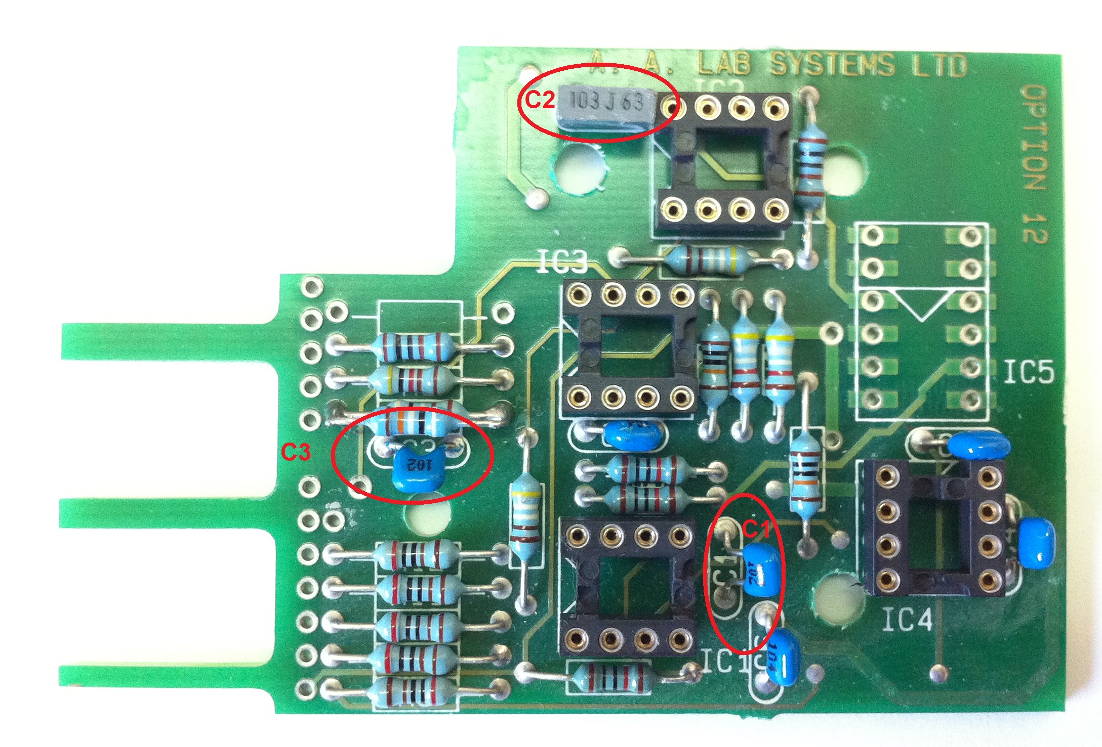
The capacitors C1, C2 and C3 determine the bandwidth of the signal conditioner. The following tables contain few common setup of signal conditioner as shipped to our customers during the last 28 years:
Basic setup = Low bandwidth, low noise. -3dB point compared to output of 10V P-P @100Hz
Capacitor Values: |
C1=1nF (102) |
C2=10nF (103) |
C3=1nF |
Gain: |
1 |
2 |
5 |
10 |
20 |
50 |
100 |
Frequency Bandwidth [KHz.] (@-3dB) |
15KHz |
16 KHz |
17 KHz |
17 KHz |
11.6KHz |
3.8 KHz |
1.62KHz |
Noise (mVptp) |
800µV |
890 µV |
1mV |
1.02mV |
1.34mV |
1.42mV |
1.5mV |
Setup 2 = Low bandwidth, low noise. -3dB point compared to output of 10V P-P @100Hz
Capacitor Values: |
C1=1nF (102) |
C2=2.2nF (222) |
C3=1nF (102) |
Gain: |
1 |
2 |
5 |
10 |
20 |
50 |
100 |
Frequency Bandwidth [KHz.] (@-3dB) |
17 KHz |
17.2 KHz |
16.3 KHz |
16.8 KHz |
17KHz |
12 KHz |
5KHz |
Noise (mVptp) |
950 µV |
1.2mV |
1.2mV |
1.3mV |
1.5mV |
1.8mV |
2.5mV |
Setup 3 = High bandwidth@low gain, medium noise. -3dB point compared to output of 10V P-P @100Hz
Capacitor Values: |
C1= not installed |
C2=1nF (102) |
C3=1nF (102) |
Gain: |
1 |
2 |
5 |
10 |
20 |
50 |
100 |
Frequency Bandwidth
[KHz.] (@-3dB) |
98 KHz |
103 KHz |
104 KHz |
104 KHz |
100 KHz |
38 KHz |
28.8KHz |
Noise (mVptp) |
1mV |
1.2mV |
1.6mV |
1.8mV |
2.9mV |
3mV |
3mV |
Setup 4 = medium-low bandwidth, low noise. -3dB point compared to output of 10V P-P @100Hz
Capacitor Values: |
C1=470pF (471) |
C2=470pF (471) |
C3=470pF (471) |
Gain: |
1 |
2 |
5 |
10 |
20 |
50 |
100 |
Frequency Bandwidth
[KHz.] (@-3dB) |
32.5KHz |
34 KHz |
34 KHz |
34 KHz |
34.4KHz |
30 KHz |
15 KHz |
Noise (mVptp) |
1.2mV |
1.12mV |
1.12mV |
1.34mV |
2mV |
3mV |
3.5mV |
IC2=AD822AN |
|
|
|
|
36 KHz |
30 KHz |
15.5 KHz |
Setup 5 = High frequency bandwidth, low noise. -3dB point compared to output of 10V P-P @100Hz
Capacitor Values: |
C1=220pF (221) |
C2=220pF (221) |
C3=220pF (221) |
Gain: |
1 |
2 |
5 |
10 |
20 |
50 |
100 |
Frequency Bandwidth
[KHz.] (@-3dB) |
70 KHz |
74 KHz |
76 KHz |
82 KHz |
76 KHz |
63 KHz |
32 KHz |
Noise (mVptp) |
1 mV |
1.02 mV |
1.4 mV |
1.5 mV |
2 mV |
3.7 mV |
5 mV |
Setup 6= Highest Frequency, higher noise. -3dB point compared to output of 10V P-P @100Hz
Capacitor Values: |
C1= uninstalled |
C2= uninstalled |
C3= uninstalled |
Gain: |
1 |
2 |
5 |
10 |
20 |
50 |
100 |
Frequency Bandwidth
[KHz.] (@-3dB) |
100 KHz |
103 KHz |
104 KHz |
104 KHz |
103 KHz |
103 KHz |
103 KHz |
Noise (mVptp) |
1 mV |
1 mV |
1.4 mV |
1.8 mV |
3.2 mV |
6.5 mV |
11 mV |
IC2=AD822AN |
|
|
|
138 KHz |
141 KHz |
135 KHz |
126 KHz |
IC2=AD822AN |
|
|
|
2 mV |
3.5 mV |
7 mV |
11 mV |
In order to change the capacitors, the cover of the channel module must be removed using 4 screws and Option 12 board must be removed gently using a flat screwdriver inserted below its socket.
After the capacitors were changed, the boards should be carefully examined to make sure that no drops of solder were left on the board. Flux drops can be cleaned using a piece of cotton with some Acetone or PCB cleaner spray. After the board is clean and dry, it should be inserted back into the channel module: Selector and trimpot should be inserted into the panel holes and then the electrical pins should be matched to the socket pins below and pressed into them. The plastic spacers should also be pressed into the appropriate holes on the board.
In some setups, U2 must also be changed.
If you cannot find capacitors in the right values, please call us and we will prepare them for you at a low cost of US$25.- per each Opt. 12 board including socket pins, U2 chip and shipping.
Please keep in mind that the anti-aliasing low pass filters are also used for limiting your frequency bandwidth and they should also be changed if you are looking for a higher frequency bandwidth. |