The AFL-6400 is an enhanced Fiber Optic Transmission product family, used for transmission of up to 16 analog channels + 32 digital channels in each direction.
The product is based on A/D and D/A technique, combined with a powerful transceiver,
for ranges of up to 100 Km, at Analog bandwidth of up to 250 KHz. per channel,
at 16 bit accuracy (96 dB S/N ratio). Each unit can work back to back with the
same type of unit as a receiver / transmitter module (i.e. for sending and receiving
analog and digital signals to the other unit) or as a powerful data acquisition
module, used for acquiring analog or digital data Over long distances, with
high accuracy and noise immunity.
All channels are sampled simultaneously to provide correct phase signal for analysis, control and data acquisition purpose.
Applications
Transfer an analog signal from a noisy environment Isolation of the signal from high voltage sources Eliminating ground loops Accuracy and high Signal/Noise Ratio Bi-directional data acquisition and control Excellent system reliability
By combining fiber optic technology with advanced proprietary hardware, A. A. Lab
Systems provides researchers and industry with the means to isolate 16 analog + 32 digital signals from electrically hostile environment, transmit it over up to 100 km to the data acquisition system, while conditioning the signal. This method eliminates the addition of noises generated by electrical machinery, line noises, ground loops and digital noise to your analog signals.
Features:
Excellent signal isolation. Prevents ground loops and computer noise effects on your Analog Signals. Transfers analog signals to distances of up to 100 Km. Linearity: better than 0.01%. Low noise; S/N ratio (DC-1KHz.): 86 dB. Input signal: Up to +/-10 Volt @ up to DC-250 KHz per channel, up to 16 channels.
(maximum signal level with no damage: +/-15V)
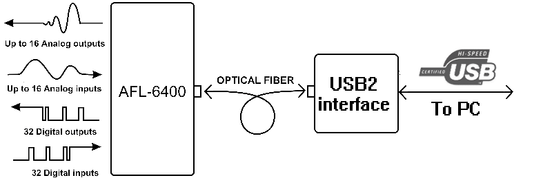
Application Sample:
The
following drawing describes how 2 Bi-Directional AFL-6416 systems can be configured
together, using a single optical fiber.
Advantages:
Low noise transfer of analog or digital data (such as RS-232 interface) particularly beneficial in electrically noisy environments and for transmission over long distance. For medical tests: the patient is isolated from data acquisition system and from any other high voltage source Optional instrumentation amplifier input stage provides a differential input, with an adjustable gain of 10-2,000, for direct connection of any sensor such as: Strain Gage, Piezo, EEG & ECG, temperature, Humidity, Pressure, etc. Isolates delicate test equipment from computer-generated noise and spikes: noises from computer do not return into your system Eliminates the formation of "ground loops" (when two instruments are connected to separate power lines or have a difference between their ground voltage potentials) Total protection of signal processor's input stage from accidental sensor malfunction (e.g. short to mains voltage or a lightning shock) Replaces bulky coaxial cables with compact fiber-optic cables - especially important when rewiring existing ducts. Cheaper wiring (for long distances) than standard copper cable. 16 Analog channels + 32 digital channels on a single fiber! Transfers analog and digital signals to distances of up to 100 km - with very high accuracy.
USB2 Data Acquisition Software:
The USB-2 interface is supported by a data acquisition, calibration and
control program.
This progream enables the user to view the input signals in real time:
See the spectral Analysis of the input signals (FFT of 2048 points):
Test the calibration of the Input and Output signals:
The program can acquire the analog and digital data to the hard drive and
convert it to ASCII
Comma Delimited files (for importation to Excell, Word processors, MatLab etc.).
The program also converts those files back to Binary files which can be sent to
the AFL-6400
and played back on the Analog and Digital Outputs (like and Analog and Digital
recorder).
Specifications:
All models:
Analog Inputs:
Input Voltage Range: -10 Volts to + 10 Volts.
Sampling resolution: 16 Bit.
Noise and hum induced in input: Less than 0.1 milliVolts RMS (DC-1KHz.).
Sampling method: True Simultaneous sampling.
Analog Bandwidth is set per customer's request.
Please note that analog Bandwidth in NOT half of the sampling rate!
Internal Low-Pass Filters are not ideal!
Analog Outputs:
Output Voltage Range: -10 Volts to + 10 Volts.
Resolution: 16 Bit.
Noise and hum induced in Output: Less than 150 microVolts RMS (DC-1KHz.).
Delay from Input to Output: 9 micro Seconds + Filter's delay.
Digital Inputs and outputs:
Number of I/O signals: 32 Inputs + 32 Outputs.
Sampling Rate: up to 792 KHz. per line.
Sampling method: True Simultaneous sampling.
Delay from Input to Output: 9 micro Seconds constant delay
Digital I/O signals can be combined with RS-232 or RS-485 drivers for bi-directional
signals.
Optical Fiber:
Up to 20 Km. Of Single mode Fiber with ST connectors. 100 Km. Transmitters and
receivers are available as Option 01.
Link Rate: 155 Mb / Sec.
Ordering Information
AFL-6400 Modules:
AFL-6404 - 4 bi-directional analog channels + 32 digital channels.
Sampling rate: 792 KHz. simultaneous sampling for all Inputs and Outputs.
Analog Bandwidth: 100 KHz. per channel.
AFL-6408 - 8 bi-directional analog channels + 32 digital channels.
Sampling rate: 396 KHz. simultaneous sampling for all Inputs and Outputs.
Analog Bandwidth: 50 KHz. per channel.
AFL-6416 - 16 bi-directional analog channels + 32 digital channels.
Sampling rate: 198 KHz. simultaneous sampling for all Inputs and Outputs.
Analog Bandwidth: 25 KHz. per channel.
AFL-6404 - 4 - RX/TX Uni-directional analog channels + 32 digital channels.
Sampling rate: 792 KHz. simultaneous sampling for all Inputs or Outputs.
Analog Bandwidth: 100 KHz. per channel.
AFL-6408 - 8 - RX/TX Uni-directional analog channels + 32 digital channels.
Sampling rate: 396 KHz. simultaneous sampling for all Inputs or Outputs.
Analog Bandwidth: 50 KHz. per channel.
AFL-6416 - 16 - RX/TX Uni-directional analog channels + 32 digital channels.
Sampling rate: 198 KHz. simultaneous sampling for all Inputs or Outputs.
Analog Bandwidth: 25 KHz. per channel.
Uni-directional systems must be ordered in pairs (RX and TX) or one side
with a USB2 interface .
OPTIONS:
Option 01 - High range fiber Optic Transmitter + Receiver - up to 100 Km.
Option 02 - Wavelength Multiplexer / Demultiplexer (WDM) for combining 2 wavelengths
on the same optical fiber (1310 and 1550 nm). This device is usefull for using
multiple AFL-500
devices on the same optical fiber or when using a Bi-directional system for
long range (for saving fiber cost).
Option 03 - Optical Coupler for using a single fiber as bi-directional link
(instead of 2 fibers) or for dividing the optical data to 2 different fibers
(2 outputs with the same optical signal).
Option 04 - AFL-6400-USB2 : A USB2 interface to AFL-6400 optic fiber. This
option enables using the AFL-6400
units as an Analog Front End, or as a part of a Data Acquisition/Monitoring
system.
The USB2 interface card may be used to acquire data and display it or
save the data to a host computer. It may also function as a transmitter to transmit
arbitrary Digital or Analog data to the AFL-6400 Digital or Analog Output. A
monitoring system may be configured in conjunction with Option 03 (AFL-6400
receives Analog and Digital signals, while the same data is recorded on a host
computer). The USB-2 Interface has a control over the sampling rate of the system,
from the maximum frequency down to 1 Hz. The USB-2 interface may be used as
a data acquisition system with one AFL-6400 Bi-Directional unit, or as a "Listener"
device in a "Back to Back" configuration of 2 AFL-6400 units (Optical
Splitter required).
POWER SUPPLIES:
AFL-6400-PS3 - 11.3 Volts, 3A low noise, linear, Regulated power supply (for
1 AFL-6400 unit)
AFL-6400-PS6 - 11.3 Volts, 6A low noise, linear, Regulated power supply (for
2 AFL-6400 units with 2 power outputs.)
AFL-6400-EXT - External Power Supply for system with 16 channels or Bi-Directional
with 8 channels.
SOFTWARE:
AFL-6400-SW - Windows XP data acquisition and control Software.
AFL-6400-LV - Lab View data acquisition and control VI drivers (open VI)
Optical Fiber:
AFL-6400- FO-20m. (for 20 m)
Optical Fiber - Single mode optical fiber with ST connector is available. Prices
are per unit of length. Up to 20 Km. For standard modules.
EMI/RFI protected Box:
The AFL-6400 can also be installed in a 19" rack suitable for use in EMI/RFI
sensitive applications. The AFL-6400
is mounted in a 19" rack, made from 2mm steel, and inside it there is an
additional Mu-Metal cage to eliminate magnetig interference (Mu metal is an
alloy with maximum magnetic permiability of 300,000):
The EMI/RFI input box may be configured with any number of Analog or Digital
inputs, according
to customer's request. All I/O lines goes through 10nF Feed-Thru connector to
eliminate any transfer of noise from or to the |
internal acquisition system.
The AFL-6400 and internal circuitry is powered by a 12V, 24AH battery, which
allows at least 5 hours of continuous operation.
The battery may be charged by external High power charger:
Aluminum 19" rack :
One or two AFL-6400 units may be installed into a 19" compatible Aluminum rack enclosure. The 19" enclosure height is 4U, it is self ventilated and low weight.
This rack is for one Bi-Directional AFL-6400 unit with 4 analog channels and 32 digital I/O.
This rack is for one Uni-Directional AFL-6400 unit with 16 analog channels and 32 digital I/O.
This rack is for two Uni-Directional AFL-6400 units with 32 analog channels and 64 digital outputs .
I/O Board:
AFL-6400-IO
The I/O board is used for connecting external signals to the AFL-6400. Contains
fast terminals (no screws!) for all Analog and Digital inputs and outputs.
AFL-6400-RELAY-RS232
This board is used for switching external loads and control purposes. The board
includes up to 16 DPDT relays (2 on-on contacts) for current up to 1.5A (4A
optional) and up to 16 RS-232 lines (up to 110Kbps, full-duplex) .
External Filter Board:
The External filter board contains 8 poles Anti-Aliasing filters and Reconstruction
filters.
Those filters are designed for enhancing the input bandwidth so the unwanted
signals will be
attenuated at -60dB at 50% of the sampling rate (according to Nyquist's theorem).
Those filters ensure that there would be no aliasing problems of the input signals
and that the output
signals will have no "stairs". Currently, those filters are available
in 3 cutoff frequencies:
150 KHz. for 4 Channels systems
75 KHz. for 8 channel systems 38 KHz. for 16 channels systems.