
A-308 LVDT Signal Conditioner / interface board
A. A. Lab System's A-308 is a High Accuracy, Low cost signal conditioner OEM board designed for any LVDT application where an analog DC voltage output is required.
There are 3 types of boards avilable:
1. Regular board for 5 or 6 wires LVDT transducer,
2. Miniature LVDT signal conditioner for 5 or 6 wires LVDT transducer manufacturers (no manual controls!)
3. Signal conditioning board for LVDT's with 4 wires only.
The boards may also be used with RVDT or half bridge sensors (3 wires) with some minor modifications.
Please note that the 4 wire board is compatible with all types of LVDT's. However, if you have the 5'th or the 6'th wire outputs, it is most recommended to use the 5/6 wire board for better accuracy and stability.
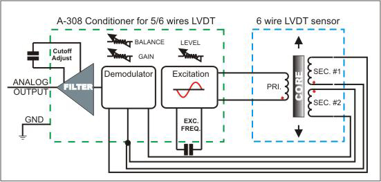
The LVDT Signal Conditioner board is a stand-alone unit. It is powered from +/- 15V DC (Other supply Voltage available per request). The LVDT transducer is connected to it via simple screw terminals (or a Molex connector on the OEM unit). The unit will output a voltage which is highly linear (0.05%) to the displacement (limited by LVDT sensor manufacturer's specifications).
The LVDT conditioner boards are designed around high accuracy ASIC that produces a low distortion Sine-wave excitation for driving the LVDT sensor. This ASIC also demodulates the signal from the LVDT sensor and converting it to a high accuracy, low noise signal, ready to interface with the highest accuracy A/D converter units. All sensitive components are thermally coupled on the silicon chip level, making the LVDT conditioner almost insensitive to temperature variations.
The LVDT signal conditioner board is also insensitive to Excitation level and Excitation loading due to a State-of the-art ratiometric measurement technology. The LVDT excitation is measured at real time and the output is compensated in real time for any changes in excitation voltage level.
The A-308 boards can operate with almost any type of LVDT sensor available when writing those lines. It's wide dynamic range (with wide range GAIN and DC Offcet controls) make it suitable for a wide range of LVDT sensors sensitivity. The adjustment of these controls is very easy and can be done by the user using a small screwdriver.
The A-308 LVDT Signal conditioner may also operate with very long LVDT wires by adding Lead/Lag compensation network (on board).
All of the A-308 models use Ratiometric measurement architecture. Most of the LVDT transducers are compatible with Ratiometric conditioning boards.
What is "Ratiometric" measurement ?
The LVDT transducer contains a primary winding (input) where a sine wave excitation is connected to and one or 2 secondary output windings.
If our conditioner board is measuring only the output voltage, we will call it a "Differential" conditioner board. When we measure the output Voltage (or the difference of the output windings) and divide it by the excitation Voltage (or the sum of the output windings), then we call it "Ratiometric" conditioner because we measure the ratio of the output to the input
(Ratio = (Va-Vb)/(Va+Vb) or Vout/Vin).
Differential operation
When operating in Differential mode, the center tap of the output windings is often not used. The output Voltage is measured across the whole transformer secondary winding. When we displace the core from the center(null position), the output will increase in phase with the excitation when moved in one direction, and out of phase with the excitation when moved to the other direction. The output AC signal is de-modulated and translated to a linear DC signal which we measure.
In Differential mode, the output DC voltage will be directly affected from the following parameters:
Operating Temperature, ambient temperature, sensor temperature, Excitation frequency, Excitation level and drift, phase shift between the excitation to the output, noises collected on the LVDT wires.
Ratiometric operation
When we want to get much higher accuracy from our LVDT sensor (at least one order of magnitude) we must use a LVDT sensor which is suitable for Ratiometric operation and a Ratiometric signal conditioning board.
When we do Ratiometric measurement, we acatually divide (in real time) the AC output of the secondary windings by the excitation AC voltage. After that, we demodulate the result and convert it to DC voltage. This technique ensure some performance benefits:
* Improved immunity to LVDT excitation level. Excitation voltage level can be changed dramatically without any effect on the demodulated output signal!
* The demodulated output is insensitive to changes of excitation frequency.
* The conditioner board is almost insensitive to errors due to temperature variations or heating of the sensor.
* The frequency and phase response are improved. You can get a higher bandwidth at the output.
* The conditioner board has higher immunity to common mode noises coming from the LVDT sensor wiring lines.
* You may change your transducer with another one, with almost no re-calibration.
What does it practically mean?
When you buy an LVDT transducer, make sure it is compatible with ratiometric conditioning boards.
If you already got such a LVDT, it means that you will not have to operate it at the maximum excitation level like the manufacturer recommends.
* Your LVDT sensor will not warm up so much if you will reduce the operating excitation voltage.
Accuracy will not change.
* Your temperature drift will be 10 - 20 times lower than with a standard differential board: 500 ppm/deg. C. in a differential conditioner board Vs. 10-25 ppm/Deg. C in a Ratiometric conditioner board.
* You don't have to worry about the null ofset drift. The output drift will not be noticeable.
* You don't have to worry about the exact frequency of operation. If your LVDT is specified at 3 KHz., for example, you will get good results if operated at 2.5 KHz. or 3.5 KHz. There would be no problem if the frequency will drift with the temperature.
* Using long wires? Your LVDT wires collect interferences (electrical noises) from motors, power supplies, computer monitors? No problem. If you use twisted pair wires, those noises will have almost no effect on your output signal quality or accuracy.
* Having phase differences between the excitation and the outputs is also not a problem using the 5/6 wire LVDT boards. The A-308 5/6 wire boards are insensitive to those phase shifts. On the 4 wires boards, Phase shifts can be compensated.
* Ratiometric winding technique reduce the body-to-stroke-length ratio for devices over 1" stroke. The meaning of it is that you can measure the same stroke with a shorter LVDT sensor!
* The temperature drift of the excitation or excitation frequency is not important because the board is measuring the ratio, not the amplitude.
Warning:
Almost 99% of the LVDT sensors manufactured today can be used with Ratiometric conditioning boards. However, in some old LVDT designs, the manufacturers do not guarantee the linearity between the sum of the output voltages to the stroke length. Those LVDTs must use the old fashioned differential conditioner boards or our universal 4 wire LVDT board or our DIN rail LVDT conditioner.
We recommend all customers to send us the datasheet of their LVDT sensor for checking that issue.
Dual
LVDT Signal Conditioner Board
Miniature
LVDT Signal Conditioner board
All boards are shown at 1:1 scale. |
|
LVDT Signal Conditioner board (For 4 wire sensor)
|
 |

The A-308 is a High Accuracy, Low cost signal conditioner board, for use with
most commercial LVDT sensors for accurate distance/position measurement. It’s
small size and high accuracy makes it an ideal solution for many applications.
FEATURES
Small
size.
Adjustable Gain, Offset, Excitation level, Excitation frequency, Bandwidth.
High linearity: 0.05%
Low drift: <50ppm/°C of F.S.
High frequency response: up to 20 kHz.
Operates with remote sensor: up to 100m.
DC output proportional to position.
Single or dual supply voltage
Built-in controls of frequency, filter, offset, gain, excitation.
SPECIFICATIONS
| DEMODULATOR | |
| Bandwidth: | up to 20 kHz |
| Linearity | better than 0.05% of FS |
| Gain Drift: | 20 ppm/°C of FS max. |
| Offset Drift: | 10 ppm/°C of FS max. |
| Output: | Unipolar or Bipolar |
| LVDT sensor type: | Any sensor with 1 Excitation coil and 2 output coils |
| Supply Voltage: | ± 15V |
| Output Voltage: | ± 10V |
| GENERAL | |
| Primary to Secondary phase shift | Insensitive |
| Transducer null voltage | Insensitive |
| Transducer cable length: | Up to 30 m |
| Output cable length: | Up to 100 m |
| EXCITATION | |
| Excitation range: | 3 - 20 V RMS |
| Excitation T.C. | 100 ppm/°C max |
| Excitation Voltage Rejection | 100 ppm/dB |
| Output Current | 40 mA RMS minimum |
| Short Circuit Current | 60 mA |
| Frequency range | 20 -20000 Hz (with component change) |
| Excitation Frequency T.C. | 200 ppm/°C |
| THD | - 50 dB |
| Excitation current may be increased to 500mA (optional). | |
| POWER SUPPLY | |
| Voltage range | ± 7V to ± 18V |
| Current (@ no load) | 18 mA |
| Temperature range: | 0 - 70°C |

For more information about our Amplifiers and Signal Conditioner products , please click here.

|


