AFL-80
Digital/Dry contact closure OEM Fiber Optic Link
AFL-80 Contact Closure Version, up to 260VAC, 16A, 4000VA max. per contact, Form C
AFL-80 TTL Version - 0-5V/0-3.3V digital signals
AFL-80 24V/1A Contact Closures, Form C
Metal enclosures are available for all models
DIN rail holders + 24VDC converters are available
Actual Size: TX:68 x 54 x 12mm, RX:109 x 83 x 12-20mm Price starts from $786.- per pair (Transmitter and receiver units, TTL I/O, boards only), basic configuration, Multi-Mode.
When you need to: Transfer 8 Digital Control signals from a noisy environment, Isolate digital signal from high voltage sources,
Control systems over a long distance, Reduce wiring costs, Get rid of interferences and spikes
Get fast and accurate response to your control signals,
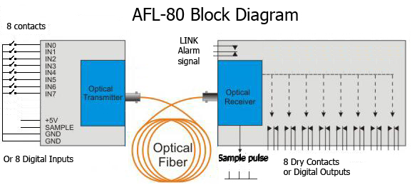
The AFL-80 digital/Dry contact fiber optic link Can tranmit 8 Contact closures or 8 TTL signals over a long range at a 150 KHz. update speed.
The AFL-80 was primarily designed for industrial and control application. The product is available in 3 versions: TTL outputs, Low current/Voltage contact closure, High current/Voltage contact closures.
TTL Version: The transmitter is
sampling the 8 Digital TTL inputs simultaneously at a rate of 180 KHz. and transmits their status to 8 digital outputs at the receiver end. 8 TTL outputs at the receiver end would be updated to exactly the same status ("0" or "1" logic level) as in the transmitter.
Contact Closure version: The transmitter is sampling the status of 8 contacts ("ON" or "OFF" status) and transmits them over the optical link to the receiver.
Those outputs are available as 8 Form C relay contacts with 2 different ratings: 24V@1A or 230VAC @ 16A.
A "LINK" alarm LED and Form C relay contact enables the user to know if the link was disconnected and take any precautions needed to halt the system. A TTL signal is available at the TTL version of the product.
Input sampling and output updates may be synchronized to external circuits or controllers by using the "SAMPLE" pin at the Transmitter or at the Receiver. This pin provides a TTL pulse every time that the input status is read (at the transmitter) or that the output status is updated (at the receiver end).
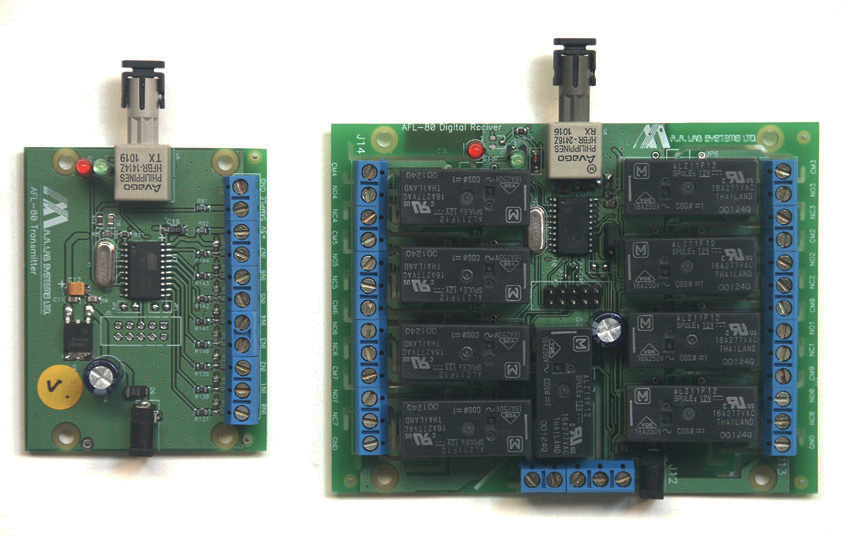
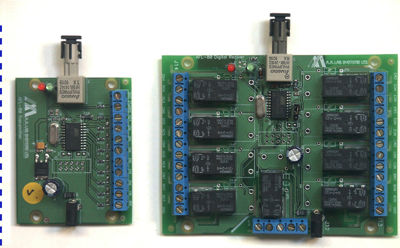
The
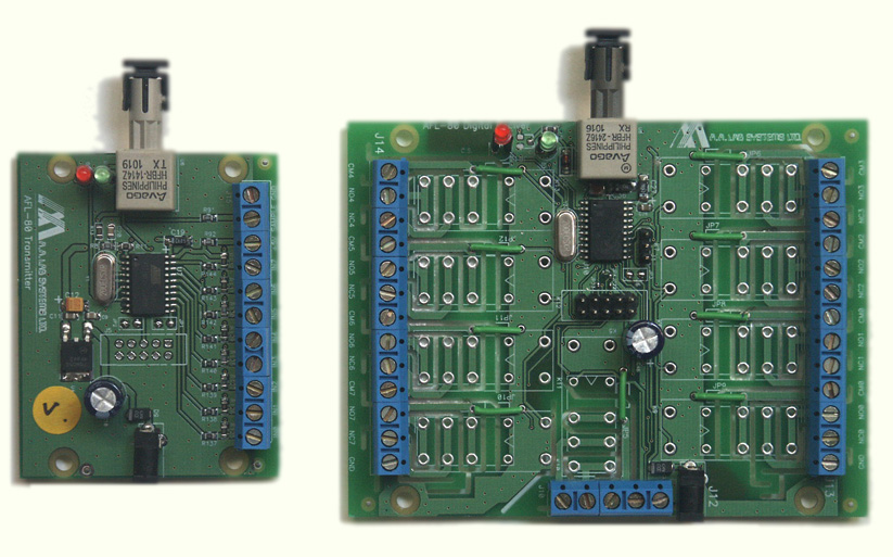
AFL-80 consists of the following components: A digital input Fiber Optic Transmitter - AFL-80/TX,
With TTL/Contact Closure compatible inputs. A digital Fiber Optic Receiver - AFL-80/RX,
This unit can be configured with Dry contacts (1 change-over per input)
or with TTL outputs. Up
to 3 km of Multi-mode glass fiber or 50 Km of Single-mode fiber (optional). Optical budget with Single Mode transceivers: 30 dB 2 power supplies of 12V - one for each side. The units can be modified to 24V + DIN rail case and holder for DIN rail mounting.
The link is connected between the inputs at the transmitter, and the Relay contact outputs at the receiver.
Features Excellent signal isolation.Prevents
ground loops and high voltage spikes Very fast response - up to 70 uSec at TTL version, 1.5-3mSec @ contact closure version. Transfers
digital control signals to distances of up to 1.6 Km (50Km with Single Mode transceivers)
Input
signal: 0-5V logic level @ DC-40 KHz (@ TTL outputs version). 3 Versions available: TTL, 24V/1A contacts, 230V/16A contacts Very small size: TX: 68 x 54 x 12mm, RX: 109 x 83 x 12-20mm Low cost: from $786.- per pair (Rx and Tx for that price! Compare!). Relay ON/Off time: Hold- 3mSec, Release- 1.5mSec (average) TTL output On/Off time: 50nSec (rise or fall time) TTL output update rate: 180,000 times per second!.
High Voltage isolation between Tx and Rx - up to millions of Volts. Form C contacts - Can be connected as Normally Open or Normally Closed
.
Advantages Low
noise transfer of digital data, particularly beneficial in electrically
noisy environments and for transmission over long distance. Equipment control at High Voltage platforms with excellent isolation. Optional Single mode transmitter and receiver allows 30dB optical budget for longer range. Transmit 8 Contact Closures or TTL lines over distances of over 50 Km (SIngle Mode fiber) Eliminates the formation
of "ground loops" (when two instruments are connected to separate power
lines or have a difference between their ground voltage potentials). Total protection of
signal processor's input stage from lightning, High Voltage spikes etc. Replaces bulky multi-wire
cables with single, compact fiber optic cable - especially important when rewiring existing
ducts. Cheaper than using 8 copper cables for distances over 100m.
Technical
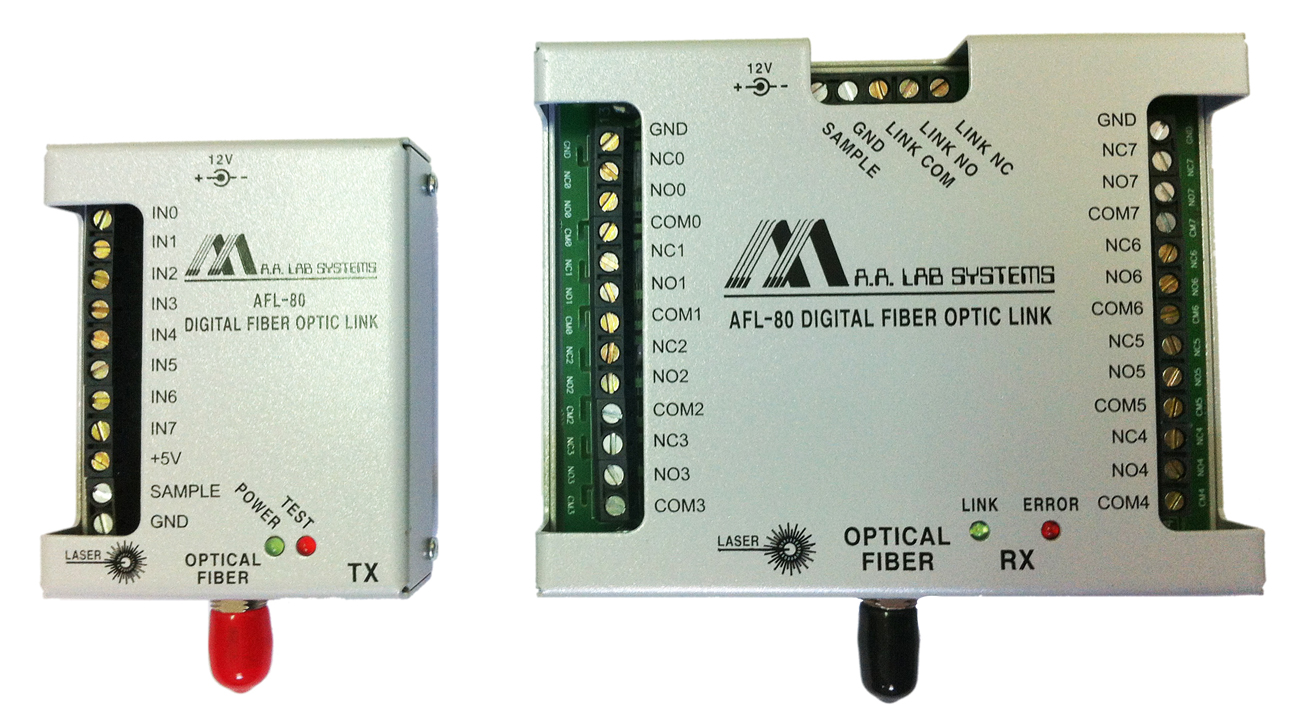
Specifications Input
Range: 0-5V logic levels related to TX common ground. Output contacts: Normally open, Common, Normally Closed.
Each relay is isolated from the others. Contacts rating:
Low Current Contacts:
24VDC @ 1A
125VAC@0.5A
Form C contacts (Common, Normally Open, Normally Closed)
High Current contacts:
260VAC @ 16A
Max. 4000VA. Form C contacts (Common, Normally Open, Normally Closed)
Frequency
Response: DC to 40 KHz (for TTL version). Timing jitter: 7 microseconds maximum Supply
Voltage: 12 V regulated,floating power supply. Can be modified to 24Vdc. Optical
Fiber: Glass, 62.5/125 micron dia. Standard (up to 3 Km), ST connector standard, SMA optional Transmission Range:
- Up to 3 Km (1.8 miles) standard(MM fiber), 50Km optional with Single-Mode transmitter Optical budget with Single Mode transceivers: 30 dB . 5V output terminal current: Up to 100 mA . Relay ON/Off time: Hold- 3mSec, Release- 1.5mSec (average) Voltage Isolation:
- Input to Output - infinite voltage isolation,
- Input/Output to Mains - 800V standard, up to 2500 V optional,
-Output to Output - over 800 Volts @ contact closure version.
- Battery operated - infinite voltage. Relay to Relay isolation voltage: 800V maximum.
Ordering
Information
The AFL-80 may be ordered with Single-Mode or Multi-Mode optical receivers and transmitters.
Single mode transmitters work in a different wavelength than Multi-mode transmitters and they cannot be combined!. They are suitable for different types of optical fibers.
If you already got a fiber installed, please check the type of fiber before placing your order. Each side needs a seperate power supply or battery. All units , on the same side, which share the same common ground, may use the same power supply
A stabilized
power supply may supply power for up to 5 (optionally
10) receivers or transmitters (with 16 I/O lines each)
EXAMPLE: TRANSMITTER
/ RECEIVER PAIR: AFL-80
- TT - REL1 - MM - R - 24V Where: TT = TTL Input voltage range(0-5V). REL1 = Relay Outputs(standard, 24V/1A).REL2 = Relay Outputs(High current/Voltage, 260VAC/16A). TT = TTL outputs. MM= Multi-Mode Transceivers. SM
= Single Mode Transceivers R
= Range in meters (length of fiber) 24V = Optional 24V power input. 12V standard.
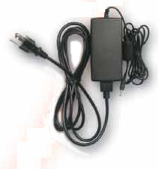
POWER
SUPPLIES AFL-80
- O3 3
channel power supply (for one side - Rx or Tx or mixed)
AFL-80-10 Power supply for powering up to 10 units(for one side)
The following options are available:
* Metal covers
* DIN rail holders
* Internal converters for 24V power input
* Singlemode optics (instead of Multi-Mode)
* Custom assembled mixed units - TTL + REL1 + REL2 in one board.
* 110VDC power supplies (usually for flamabe environment)
* Power splitters - allows sharing of power supplies for few modules.
AFL-80-BAT
Battery
operated power supply:
Can run 6 Transmitters or 3 Contact Closure Receivers for up to 10 hours.Includes
a 12 V/ 6.5 AH battery, charger + cables. Other batteries available per request. Available in OEM version:
Or housed in metal case:
Optical cables are available. Standard lengths are: 2,10,20,50,100m
For more information about other Analog/Digital fiber optic links click here.