
A-310
High Voltage, High power Amplifier/ Piezo Driver
The A-310 piezo Driver/Piezo Amplifier is a high Voltage, fast
Piezo Driver / Linear Amplifier for high power applications.
It was especially designed as a Linear Amplifier / Driver for high capacitance PIEZO Electric
Actuators (also known as "Piezo Amplifier"), stacks,piezo sheets, bimorph elements
and other devices.
The Piezo Driver / Piezo Amplifier is based on a high voltage, high frequency
and high current MOSFET amplifier which is capable of driving up to ±95V
(190V ptp) at ±2.5A at frequencies from DC to 250 kHz.
The A-310 amplifier is available in 2 configurations:
1. Single amplifier +/-95V output, +/-2.5A output current,DC- 250KHz. Frequency Bandwidth.
2. Dual amplifier - 2 independent amplifiers with independent inputs and outputs., +/-95V
outputs, +/-1.25A output current capability, DC-250 KHz. Frequency bandwidth.
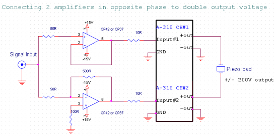
By connecting 2 amplifiers in inverting, differential connection to a floating load, up to +/-190V @ +/-1.25A can be delivered to the load (~240W peak or ~120W RMS).
The amplifier section is very stable and has a very low
electrical noise - Compare Our Specifications!


This High speed Amplifier / Driver can be used for Various applications
requesting high frequency, High Voltage and fast response as:
Plasma Driver and Plasma Actuation, driver for piezo manipulator, Optical Switching
devices, closed loop feedback systems, vibration control, structural damping
analysis, Flow actuation and control etc.
Features:
![]() High frequency amplifier -
High frequency amplifier -
DC-250KHz .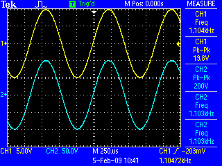
![]() Very Low Electrical
Noise-
Very Low Electrical
Noise-
<5mVptp
![]() Low Distortion
Low Distortion
<0.01% @ (DC-1KHz)
![]() High Slew rate-
High Slew rate-
150 Volts/microsecond.
Output Vs. Input @ 1KHz. Sine wave
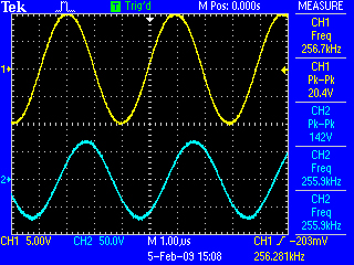
Output Vs. Input @ 250KHz. Sine wave
Specifications:
A-310 High Power Piezo Amplifier
| Amplifier section: | |
Maximum
Input Voltage |
± 12 V |
|---|---|
Maximum
Output Voltage |
± 95 V (190Vptp) |
Maximum
Current |
± 2.5A (+/-1.25A in dual amp configuration) |
Bandwidth |
Into
1 K |
| DC to 250 kHz (-3 dB) | |
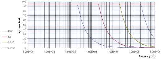
| Into Capacitive load (single amp): | |
| DC to 250 kHz (- 3 dB) (0 to 20nF) | |
| DC to 75 kHz (- 3 dB) ( 50 nF) | |
| DC to 38 kHz (- 3 dB) (0.1 µF) | |
| DC to 3500 Hz (-3 dB) (1 µF) | |
| DC to 350Hz (-3 dB) (10 µF) | |
Output
Power |
~250 Watt Peak |
DC
Gain |
10 (up to 50 optional) |
Coupling |
Input & Output: Direct DC Coupling |
DC
Offset |
Adjustable to ± 90 Volts (RTO)+ On/Off Switch |
Input
Impedance |
10
K |
Slew
Rate |
150V/ µSec |
Output
Impedance |
1 |
Output
Noise (input shorted, 250 KHz. Bandwidth) |
6 mV PTP max. (1.3 mV RMS max.) |
Variable
Gain Option: |
0-10X
or 0 - 20X or 0-40X available. Please consult the factory regarding that option. |
AC
Input |
|
Line
Input Voltage |
110/120
V, 60 Hz or 220/230 V , 50/60 Hz. |
Line
Input Current |
6 A peak (@220VAC) |
| Options: | |
| 01- One channel, +/-100V @+/-2.5A | 1 input, 1 output |
| 02-Dual channel, +/-100V @ +/-1.2A X2 | 2 inputs, 2 outputs |
| 02-Higher Gain | Up to 50 |
| 04-Variable Gain | 0-10X or 0 - 20X - No Charge. |
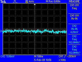
The Standard amplifier has very low noise. Noise level @ 250 KHz. BW, input shorted --> display set @ 5 mV/div. 100nS/div. Total noise is less than 1mV RMS ! |
|
Output
Noise - 250 KHz. Bandwidth |
|
he amplifier/s are housed in a standard 19" rack enclosure, 4U height.
Weight: 24 Kg.
Applications:
2 amplifiers can be connected in series or in parallel
in order to double the Output Voltage or Output Current.
Series connection (+/- 400V into a floating load = 800V ptp).
Calulating the estimated current needed to drive your load:
| In order to purchase the right amplifier to drive your load, you must calulate the peak current needed. | |||
| For Capacitive load: | |||
|
|||
| F=Maximum frequency (Hz.) π=3.1415927 |
C=Capacitance in Farads Vpeak=Maximum Voltage you need to drive your Load. |
||
| For Resistive Load: | |||
| I = Vpeak/R | |||
| where R is the resistance of your load in Ohms. | |||
The current, Voltage and Frequency must be less or equal to the amplifier's specifications.
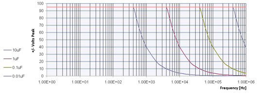
Frequency Response curve for various output configurations and loads:
2 Bi-Polar amplifiers, +/-95V @ 1.25A:
1 Bi-Polar amplifiers, +/-95V @ 2.5A:
A-310 safe operating limits:
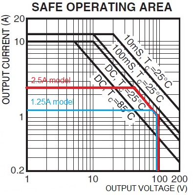
This amplifier is NOT SUITABLE for driving pure inductive loads
(i.e. speakers, solenoides, electromagnets etc.)
Internal power dissipation: 100W dc.
You must connect your load with thick wires to minimize inductance (like speaker wires). Coaxial cable is not recommended for cables over 2m (6.5 Ft.) because the capacitance of the cable (15-50 pF/Ft) will load your amplifier at high frequencies.
| Example: The active impedance of a capacitive load is given by the equation: Z=1/(2*Pi*F*C) where Pi=3.1415, C in Farads, F in Hz.The user must check that under the peak operation Voltage, at maximum frequency, the current will not exceed 2500mA (2.5A). Example: Output Voltage is +/-100V, Maximum Frequency=20KHz. Load is 100nF. Z=1/(2*3.1415*20,000*100EE-9) =79.6 Ohms. 100[V]/80[Ohm] =1250[mA] ===>The single channel amplifier will drive that load at an amplitude of 100V (200V ptp). For the dual channel amplifier, this load is marginal because the current capacity is only 1200mA. |
Fast shipping!!!
We use DHL for shipping. It takes up to 3 working days to ship by DHL to any country.
We accept VISA, MaterCard, American Express. Your credit card is charged only after we ship the order.
Please contact us for further information and a price quotation:
CONTACT US
For more information about our Amplifiers and Signal Conditioner products , please click here.

|


